Modeling a spherical space using "N+2" loudspeaker geometry
posted 2006.06.01

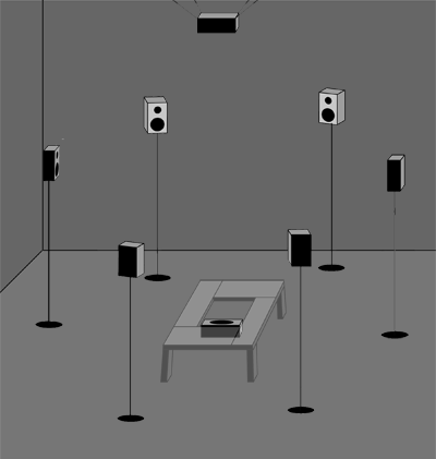
Figure 1.
"N+2" configuration, with N=6.
This speaker configuration simulates sound sources that are distributed across the surface of a sphere. We arrange N speakers evenly around the equator of the listening space in a ring of radius R, with the speakers located at approximately the same height as the listener’s head. An additional speaker is situated overhead ("North") at a height R above the equator; another is at the center of the floor ("South"). (Ideally, the South speaker would be situated a distance R below the equator, but this is usually impractical, as it might require the South speaker to be located some distance below the floor.) By splitting the audio signal into polar and equatorial components, and routing these to the appropriate speakers, the phantom image can be placed quite convincingly anywhere on the sphere.

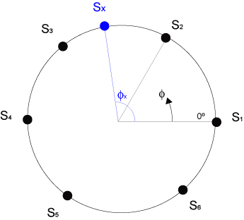
Figure 2.
Phantom image position (equatorial component),
looking down from above the North Pole. Here N=6.
Figure 1 illustrates the equatorial speaker layout for N = 6. An equatorial view of this configuration is shown in Figure 2. Speakers are numbered S1, S2, ... SN counter-clockwise, starting at azimuth (longitude) zero. In Figure 2 the view is looking down from above — i.e., from above the North Pole. Note that the azimuth φ increases counter-clockwise. This is the same convention used in geographic coordinates, in which longitude increases eastwards (CCW as viewed from above the North Pole).
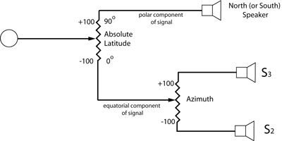
We begin by splitting each source signal into two components — polar and equatorial — using the mixer circuit shown in Figure 3. The first pot ("Absolute Latitude") is panned according to the absolute geographic latitude of the source: a source on the equator would be panned to -100; a source at one of the poles would be panned to +100; a source at 45°N (or 45°S) would be panned to 0; and so on. (For our purposes, we can safely ignore the curvature of the sphere when panning, and simply pan linearly in proportion to the latitude. Curvature-related panning errors are hardly noticeable to the ear.) The polar component of the signal is then sent to the North or South speaker, as appropriate.

Figure 3.
"N+2" signal path for one channel.
The equatorial component of the signal is routed to a second pot and panned to the correct location between two adjacent equatorial speakers.
A practical illustration, using N=6
Consider a "6+2" speaker array, as pictured in Figures 1 & 2. The IDA seismic station TLY is located in Talaya, Russia at 52°N, 104°E. Where exactly do we place its signal in this sound installation?
First we consider the latitude. TLY’s absolute latitude is 52°, so the first pot should be panned to +16 (because 52÷90 = (16-(-100))÷200). Because TLY is in the northern hemisphere, we know to send its polar component to the overhead (North) speaker.
TLY’s longitude (φx= 104°) lies in the second sector of the equatorial ring, between speakers S2 (60°) and S3 (120°). (Sx in Figure 2). We will therefore pan its equatorial component linearly between these two speakers. The pan setting, p, for the second pot is found thus: (104°-60°)÷(120° - 60°) = ((p-(-100)) ÷ 200), or p=+47.
To summarize: Using the mixer circuit in Figure 3, station TLY (52°N, 104°E) would have pan pot settings of +16 (North speaker) and +47 (between speakers S2 and S3).
N.B.: If you’re accustomed to thinking in stereo, you may be tempted to think of S2-S3 as a stereo pair. If so, keep in mind that S2 is the right channel in Sx’s sector, while S3 is the left. Panning from -100 to +100 moves the image from from S2 to S3 — right to left to a listener inside the ring. This is contrary to the usual panning convention, in which panning from -100 to +100 moves the image from left to right.
In the present geometry, which simplifies the mapping of geographic coordinates to speaker positions, everything increases counter-clockwise and right to left: azimuthal angle, speaker number, and panning value.